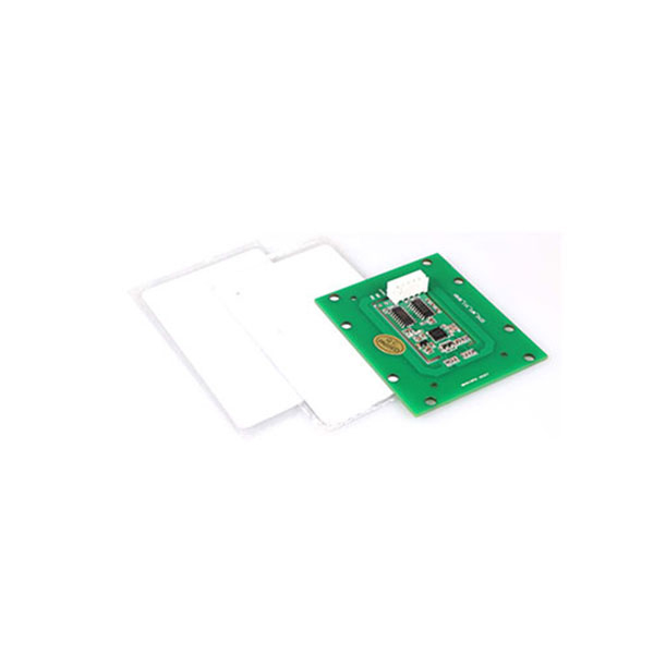
适用于 EKEPC3/EKEPCB2/EKEPCB3 控制器的射频识别模块和卡
询价

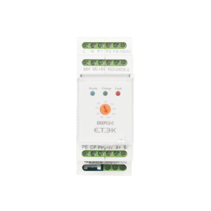
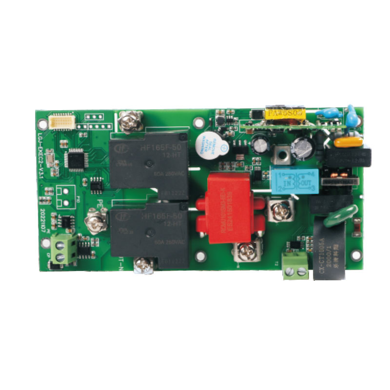
EKEPC2-C/S 是模式 3 级 2 的 EPC 电动汽车充电控制器,用于连接控制负载通断的交流接触器,最大电流可达 63 安培。

EKEPC2控制器采用Modbus-RTU协议,支持RS485通信,可通过通信向充电器发送读写命令。该控制器的附加功能包括:非接触式IC卡连接模块、剩余电流监测单元、DLB管理、液晶显示屏、电度表、电子锁、外部紧急停止按钮等。订购时需注意这些功能。
| 模型规格说明 | EKEPC2 客户端/服务器版 |
| 工作电压 | 交流 230 伏±10% 50 赫兹 |
| 输出 PWM 信号 | 10A,16A,20A,25A,32A/63A |
| 输出控制交流接触器 | 被动触点 |
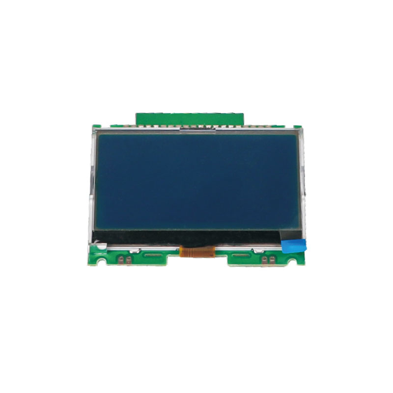
| 附加连接功能(可选) | 1.RCMU 泄漏监测模式(交流 30 毫安 + 直流 6 毫安)2. 非接触式 IC 卡 3. DLB 当前余额模式 4. 电流传感器接入模式(直流 +12V 输出 0 – 5V) 5. 带有液晶显示屏 |
| 通信功能(可选) | 1 路 RS485(Modbus-RTU)/RS232 2 路 RS485(Modbus-RTU)/RS232(主从模式) |
| 输出辅助电压 | DC12V/100mA、DC5V/100mA |
| 环境温度 | -40℃ ~+70℃ |
| 湿度 | ≤85% |
| 知识产权学位 | IP22 |
| 冷却方法 | 自然冷却 |
| 安装方法 | DIN 导轨标准 |
| 重量 | 40g |
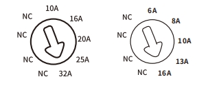 |
最大充电容量选择 10A、16A、20A、25A、32A,通过拨盘开关 |
控制器特性
EKEPC2 – C/S控制器是一种适用于电动汽车充电桩的产品。
选择控制器附加功能:
将拨码开关切换到“ON”,对应所需功能。
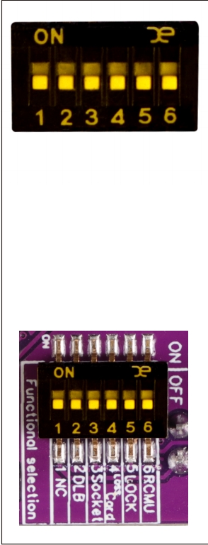
对应位置的功能描述如下:
“ON”位置:
“OFF”位置:
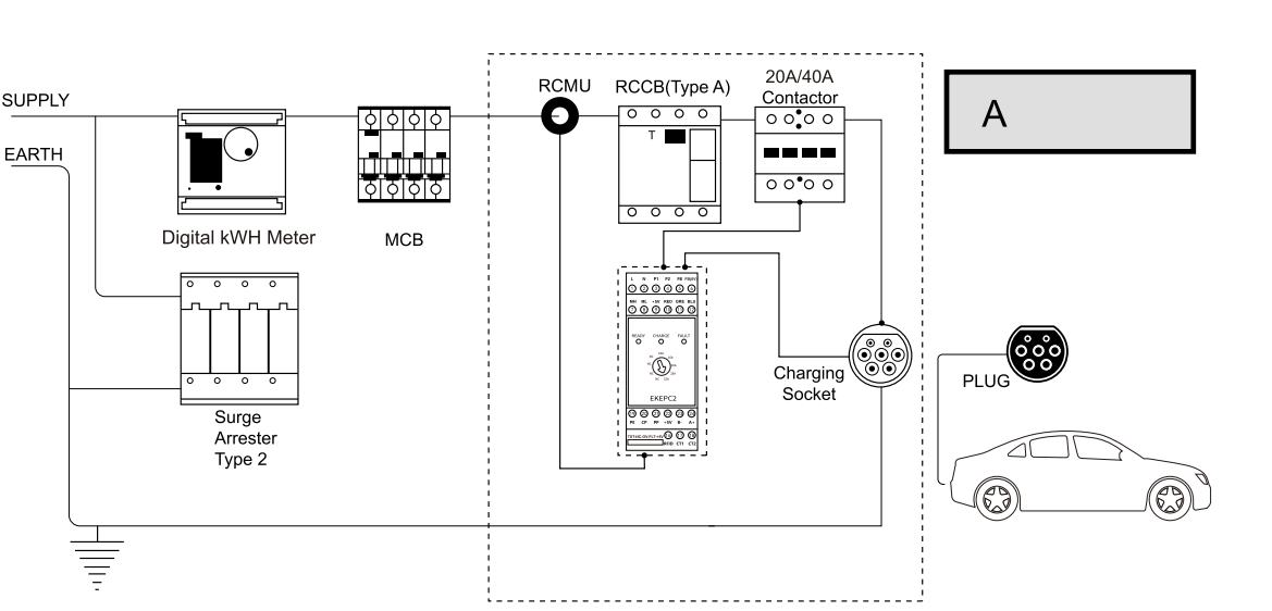
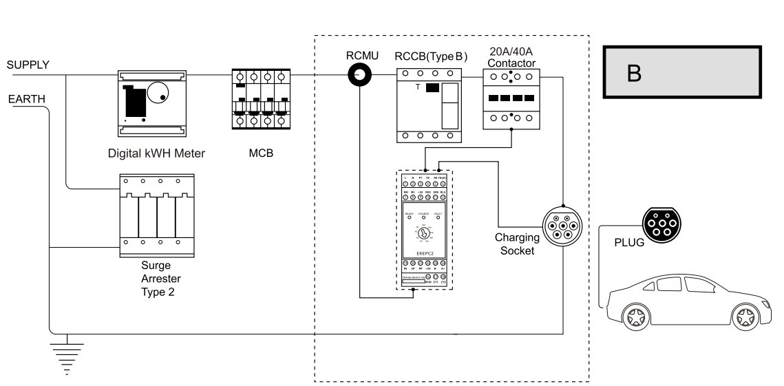
EKEPC2 – C/S EVSE控制器 应用案例
以下是一个应用案例的示意图。
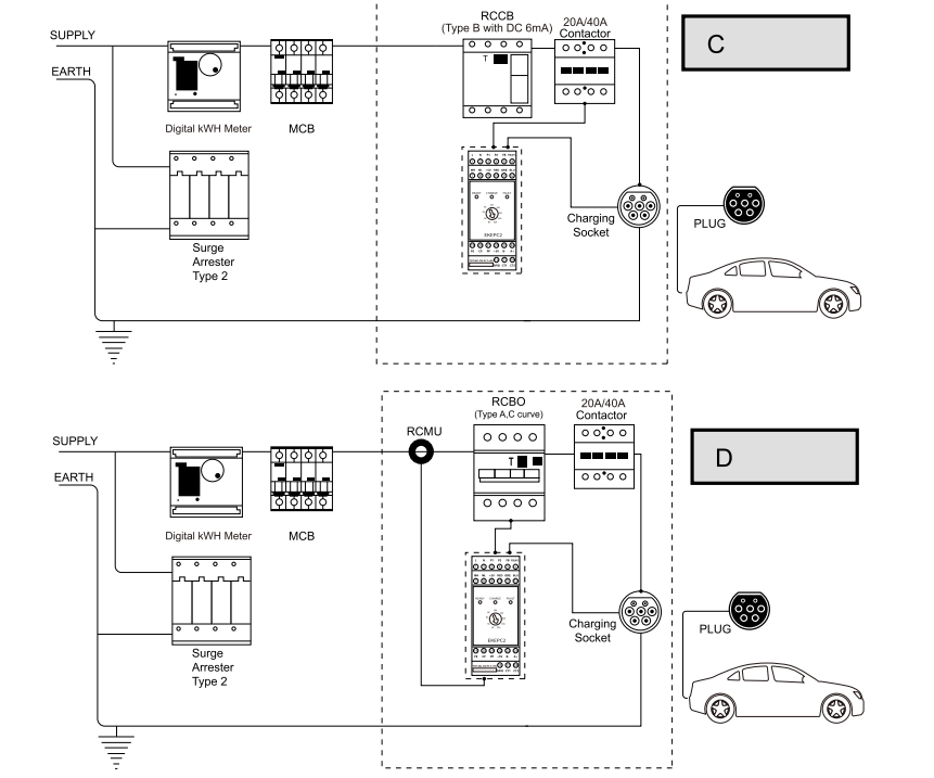
EKEPC2 – C/S EVSE协议控制器连接状态
| No. | State Code |
LED Color | LED State | PE、CP、PP state | Controller state | Remark |
| 0 | K | Red | 5Hz flashing | Power self detect failed | Fault–1# | Power self-check failed! Please turn the power back on! |
| 1 | A | Blue | 1Hz flashing | CP disconnection | Ready | |
| 2 | l | Blue | 2Hzflashing | Waiting for IC card | RFID Waiting | |
| 3 | B | Blue | Stabilization | CP connect to diode+2.7KQ | Connected | |
| 4 | B | Blue | Stabilization | CP connect to diode+1.3KQ | Connected | |
| 5 | C | Green | Green brightening | CP connect to diode+2.7KQ parallel connect1.3KΩ |
Charging | |
| 6 | D | Red | Stabilization | CP connect to diode+2.7KQ parallel connect 1.3KQ parallel connect 270F Or CP connect to diode+270R Or CP connect to diode+270R parallel connect 2.7KQ Or CP connect to diode+270R parallel connect 1.3KQ |
Fault–2# | Need Ventilation! |
| 7 | F | Red | 1Hz flashing | CP line short circuit with PE line | Fault–3# | CP-PE short circuit! Please check the CP line |
| 8 | H | Red | 5 Hzflashing | RCMU occurs residual current or self detect failed | Fault–4# | RCMU leakage or self-inspection failure |
| 9 | E | Red | 2Hzflashing | Diode short circuit (Requirement waiting the CP disconnected) |
Fault–5# | EV-Charing Socket Fault |
| 10 | G | Blue+Red | 2Hzflashing | PP line disconnection | Fault–6# | SPLIT PP wire, Please check the PP line |
| 11 | J | Red+Green+Blue | 2Hzflashing | Electromagnetic Lock failed | Fault–7# | Electronic Lock Disabled |
| 12 | L | Blue | 5Hzflashing | IC card failed | Fault–8# | RFID card is not valid |
| 13 | M | Red+Green | 1Hzflashing | Circuit overload,DLB Mode activated | Fault–9# | Circuit overload DLB Mode activated |
EKEPC2-C/S 电动汽车充电控制器 RS485 通信说明
Modbus 通信协议,波特率:9600,8 位数据位,无校验位,1 位停止位 地址:1 – 255 默认:255(广播地址)
| Register address | Data description (power failure protection) | (R/W) | type of data | Defaults |
| 86 | Overvoltage protection value (0.01V) | R/W | 16-bit integer | 26500 |
| 87 | Under-voltage protection (0.01V) | R/W | 16-bit integer | 16500 |
| 88 | Overcurrent protection value (XX%) | R/W | 16-bit integer | 120 |
| 89 | Remote start and stop (0 invalid, 1 start, 2 stop) | R/W | 16-bit integer | 0 |
| 90 | 1# Meter A-phase voltage address number (65535 is an invalid address) | R/W | 16-bit integer | 65535 |
| 91 | 1# Meter B-phase voltage address number (65535 is an invalid address) | R/W | 16-bit integer | 65535 |
| 92 | 1# Meter C-phase voltage address number (65535 is an invalid address) | R/W | 16-bit integer | 65535 |
| 93 | 1# total current address number (65535 is an invalid address) | R/W | 16-bit integer | 65535 |
| 94 | 1# total power address number (65535 is an invalid address) | R/W | 16-bit integer | 65535 |
| 95 | 1# Total KWH address number (65535 is an invalid address) | R/W | 16-bit integer | 65535 |
| 96 | 2# DLB current address of the meter (65535 is an invalid address) | R/W | 16-bit integer | 65535 |
| 97-99 | spare | R/W | 16-bit integer | 0 |
| 100 | Device address number | R/W | 16-bit integer | 255 |
| 101 | DLB maximum startup current (0.01A) | R/W | 16-bit integer | 3500 |
| 102 | DLB maximum protection current (0.01A) | R/W | 16-bit integer | 4500 |
| 103 | Maximum current of DLB current transformer (0.01A) | R/W | 16-bit integer | 10000 |
| 104 | DLB current sampling calibration coefficient | R/W | 16-bit integer | 1270 |
| 105-108 | spare | R/W | ||
| 109 | Max Output Current PWM Duty cycle(*100) | R/W | 16-bit integer | 9000 |
| 110 | RCMU function selection 0 disable 1 enable, other values are selected by DIP switch | R/W | 16-bit integer | 3 |
| 111 | RFID function selection 0 disable 1 enable, other values are selected by DIP switch | R/W | 16-bit integer | 3 |
| 112 | Lock function selection 0 disable 1 enable, other values are selected by DIP switch | R/W | 16-bit integer | 3 |
| 113 | Cable function version selection 0 disable 1 enable, other values are selected by DIP switch | R/W | 16-bit integer | 3 |
| 114 | DLB function selection 0 disable 1 enable, other values are selected by DIP switch | R/W | 16-bit integer | 3 |
| 115 | PID control parameter P of DLB | R/W | 16-bit integer | 100 |
| 116 | PID control parameter I of DLB | R/W | 16-bit integer | 1 |
| 117 | PID control parameter D of DLB | R/W | 16-bit integer | 100 |
| 118-119 | Controller ID number Up to 9 digits | R/W | 32-bit integer | 0 |
| 120 | Temperature correction (how much difference is input) H | R/W | 16-bit integer | 1024 |
| 121 | R/W | 16-bit integer | 0 | |
| 122 | Release temperature protection value | R/W | 16-bit integer | 600 |
| 123 | Maximum temperature protection value | R/W | 16-bit integer | 700 |
| 124 | Frequency correction (how much difference is input) | R/W | 16-bit integer | 65528 |
| 125 | Duty cycle correction (how much difference is input) | R/W | 16-bit integer | 0 |
| 126 | Trademark selection 0 none 1WATT 2VOLU | R/W | 16-bit integer | 0 |
| 127 | Pole selection: 1P 3P Default: 1 | R/W | 16-bit integer | 1 |
| 128 | The first gear current setting value PWM | R/W | 16-bit integer | 1667 |
| 129 | The second gear current setting value PWM | R/W | 16-bit integer | 2167 |
| 130 | The third gear current setting value PWM | R/W | 16-bit integer | 3333 |
| 131 | The Fourth gear current setting value PWM | R/W | 16-bit integer | 4167 |
| 132 | The Fifth gear current setting value PWM | R/W | 16-bit integer | 5333 |
| 133 | The sixth gear current setting value PWM | R/W | 16-bit integer | 5333 |
| 134-139 | spare | R/W | ||
| 140 | Software version number | R | 16-bit integer | 1002 |
| 141 | Current working status: Corresponding status 0-11 | R | 16-bit integer | |
| 142 | PWM value for cable gauge | R | 16-bit integer | |
| 143 | RCMU status 00 is not selected 01 works normally 02 self-test failed 03 charging circuit has leakage | R | 16-bit integer | |
| 144 | RFID status 00 Not selected 01 IC card not operating 02 IC card closed 03 IC card open | R | 16-bit integer | |
| 145 | RFID status 00 Not selected 01 IC card not operating 02 IC card closed 03 IC card open | R | 16-bit integer | |
| 146 | Current value of the DLB function | R | 16-bit integer | |
| 147 | Current value of charging pile 0-200.0A | R | 16-bit integer | temporarily invalid |
| 148 | Current voltage value of charging pile) 0-500.0V | R | 16-bit integer | temporarily invalid |
| 149 | Current power value of charging pile 0-22000W | R | 16-bit integer | temporarily invalid |
| 150 | Calibration value AD value of reference current | R | 16-bit integer | temporarily invalid |
| 151 | PWM duty cycle corresponding to the current set by the rotary switch | R | 16-bit integer | |
| 152 | Current output PWM duty cycle | R | 16-bit integer | |
| 153 | CP positive voltage | R | 16-bit integer | temporarily invalid |
| 154 | CP negative voltage | R | 16-bit integer | temporarily invalid |
| 155 | Overcurrent count | R | 16-bit integer | temporarily invalid |
| 156 | Small current count | R | 16-bit integer | temporarily invalid |
| 157 | Current Temperature | R | 16-bit integer | |
| 158 | temperature AD | R | 16-bit integer | temporarily invalid |
| 159 | 1# meter A phase voltage | R | 16-bit integer | |
| 160 | 1# meter B phase voltage | R | 16-bit integer | |
| 161 | 1# meter C phase voltage | R | 16-bit integer | |
| 162 | 1# meter current | R | 16-bit integer | |
| 163 | 1# total power of the meter | R | 16-bit integer | |
| 164-165 | 1# The total electricity of the meter | R | 32-bit integer | |
| 166 | 2# The current on the DLB meter | R | 16-bit integer |
注意:1)寄存器地址:90 – 95 寄存器值为:a) = 65535,此时地址无效,所有数据将依照控制器设定值进行显示和判断。b) = 当外部通信地址为 1 时,控制器将读取电表中的相应值。见下表 1
如果启用了 DLB 功能且寄存器 96 的数据为 a) = 65535,控制器将读取外部电流互感器的采样值。b) = 具有外部通信地址 2 的电流表中电流值的寄存器编号,控制器将读取电流表中的电流值。请参见下表 1。
表1:
| Name | Addr(Dec) | Length | Property | Type | Controller address |
| L 1 phase voltage | 2304 | 4 | Float | R | 90 |
| L 2 phase voltage | 2306/65535 | 4 | Float | R | 91 |
| L 3 phase voltage | 2308/65535 | 4 | Float | R | 92 |
| L 1 phase current | 2310 | 4 | Float | R | |
| L 2 phase current | 2312/65535 | 4 | Float | R | |
| L 3 phase current | 2314/65535 | 4 | Float | R | |
| Average current | Jun-18 | 4 | Float | R | 93 |
| Sum of three-phase current | 2320 | 4 | Float | R | |
| Total active power | 2322 | 4 | Float | R | 94 |
| L1-2 line voltage | 2324 | 4 | Float | R | |
| L1-2 line voltage | 2326 | 4 | Float | R | |
| L1-2 line voltage | 2328 | 4 | Float | R | |
| Three-phase line voltage average | 2330 | 4 | Float | R | |
| There is always power | 2332 | 4 | Float | R | 95 |
| Name | Addr(Dec) | Length | Property | Type | Controller address |
| Average current | 2318 | 4 | Float | R | 96 |
| Maximum current | 2334 | 4 | Float | R | 96 |
表 2:
| Name | Addr(Dec) | Length | Property | Type | Controller address |
| L 1 phase voltage | 0 | 4 | Float | R | 90 |
| L 2 phase voltage | 2 | 4 | Float | R | 91 |
| L 3 phase voltage | 4 | 4 | Float | R | 92 |
| L 1 phase current | 6 | 4 | Float | R | |
| L 2 phase current | 8 | 4 | Float | R | |
| L 3 phase current | 10 | 4 | Float | R | |
| Average voltage | 42 | 4 | Float | R | |
| Average current | 46 | 4 | Float | R | 93 |
| Sum of three-phase current | 48 | 4 | Float | R | |
| Total active power | 52 | 4 | Float | R | 94 |
| L1-2 line voltage | 200 | 4 | Float | R | |
| L1-2 line voltage | 202 | 4 | Float | R | |
| L1-2 line voltage | 204 | 4 | Float | R | |
| Three-phase line voltage average | 2.6 | 4 | Float | R | |
| There is always power | 342 | 4 | Float | R | 95 |
| Name | Addr(Dec) | Length | Property | Type | Controller address |
| Average current | Jun-46 | 4 | Float | R | 96 |
| Max. current | 396 | 4 | Float | R | 96 |
EKEPC2 – C/S 通信消息示例:DLB最大电流变更
将DLB中设置的最大电流更改为60.00A(6000),并将寄存器地址编号更改为102(66H):
上位机发送:FF 06 00 66 17 70 72 1F
地址 + 功能码 + 起始地址编号高位 + 起始地址编号低位 + 数据高位 + 数据低位 + CRC校验
控制器回复:FF 06 00 66 17 70 72 1F
地址 + 功能码 + 起始地址编号高位 + 起始地址编号低位 + 数据高位 + 数据低位 + CRC校验
3.2 读取设备序列号(2022010158 — 7885 6D2E):
上位机发送:FF 03 00 76 00 02 30 0F
控制器回复:FF 03 04 (6D 2E 78 85) 7A FA
其他数据包格式,请参阅Modbus国际通信协议标准。
安装
端子功能规格
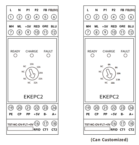
| S/No. | Mark | function | Specification |
| 1 | L | Live line | Product working power supply:AC230V±10%50Hz |
| 2 | N | Neutral line | |
| 3 | P1 | Relay/contactor Al connect to L P1connect to N |
AC contactor connected to the connection load of charging station |
| 4 | P2 | Relay coil A2 | |
| 5 | FB | Reflect signal of the electromagnetic lock |
This is the feeback signal on the electromagnetic lock directly to the passive contact output terminal of the electromagnetic lock |
| 6 | FBOV | ||
| 7 | MH | Electromagnetic lock positive voltage | Provide positive and negative pulse voltage of electromagnetic lock,duty cycle outputpulse(1:3)and total pulse output maximum driving capacity of 500ms |
| 8 | ML | Electromagnetic lock negative voltage | |
| 9 | +5V | DC+5V | External indicatorlight,DC5V/10mA drive capability |
| 10 | RED | Red LED | |
| 11 | GRE | Blue LED | |
| 12 | BLU | Green LED | |
| 13 | TST NC OV |
RCMU fault signal(DC5V), output terminal |
When the controller detects this end signal,means this line occur fault (including≥DC6mA eakage signal),the controller will cut off the charging power,untill this fault signal is solved,the controller will automatic resumes the charging state |
| 14 | FLT | RCMU test signal(DC5V), | The controller outputs the test signal before each charging,using to check that the working ot |
| 15 | +5V | the input terminal | the RCMU whether normal |
| 16 | RFID | RFID-controlied input signal | The signal of external non-contact IC card reading module,input is TTL voltage signal,DC 3.3V/5V |
| 17 | CT1 | Current transformer | When the controller requires DLB function,it requires connect to current transformer signal,the signal is:AC0-5A.This function can dynamically balance the power load,adjust the outputin time, control the charging current,and protect the safety of the power supply line |
| 18 | CT2 | ||
| 19 | PE | Power supply | Earth terminal |
| 20 | CP | Connect to the vehicle CP | Communication connection with electric vehicle,output PWM wave |
| 21 | PP | Charging cable current dentification |
When this end is a socket type charging station, t identify the current specification of charging cable |
| 22 | +5V | +5VPower Supply | Supply DC5V/100mA power output |
| 23 | A+ | A+for RS485 Communications | It can communicate with RS485 equipment.The communication standard conforms to Modbus-RTU slave mode.Baud rate:38400,N,8,1 address number default:255(Broadcast address) See Table A for details |
| 24 | B- | B-for RS485 Communications |
EKEPC2 – C/S电动汽车充电控制器接线
单相接线

三相接线
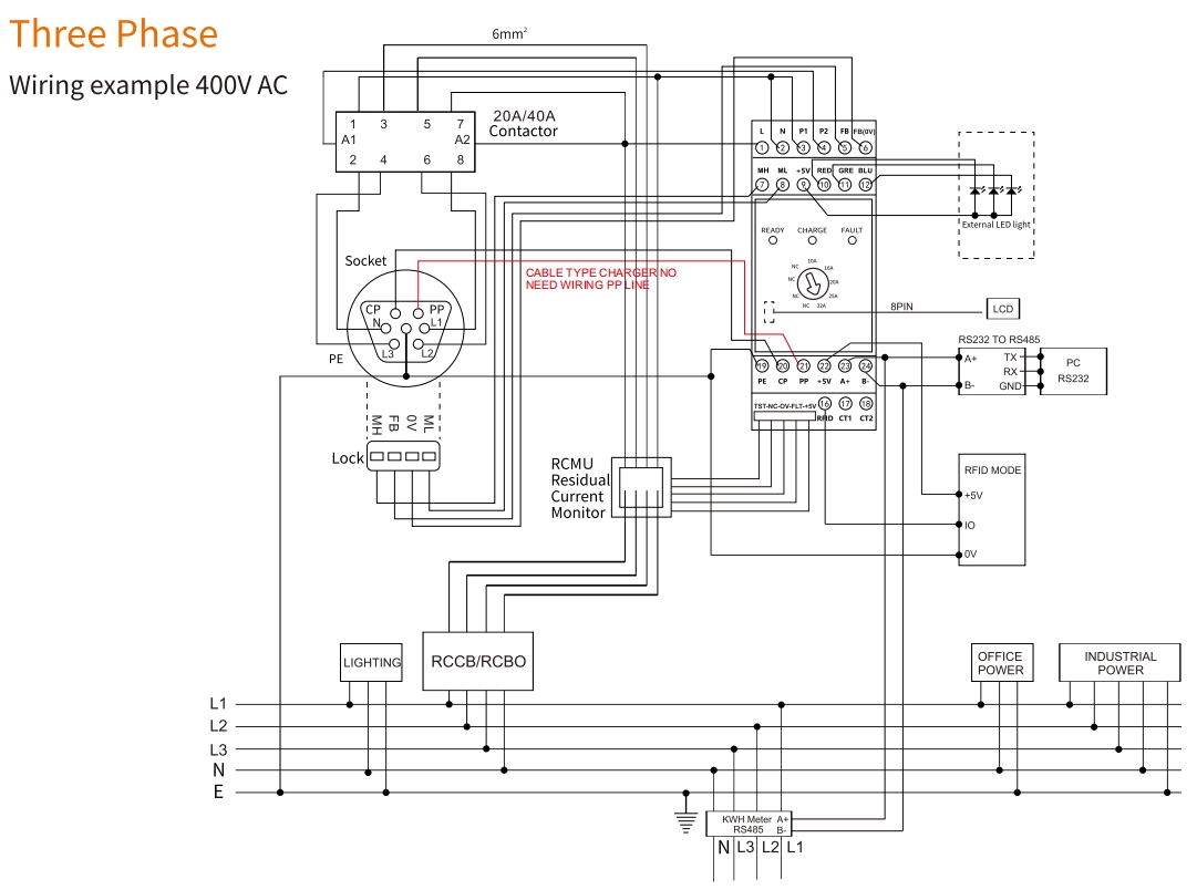
接线说明
| Rated Current | Main Circuit Cable | Controller Circuit Cable | PP/CP Cable |
| 16A | 2.5 mm² | 1.5 mm² | 0.5 mm² |
| 32A | 6 mm² | 1.5 mm² | 0.5 mm² |
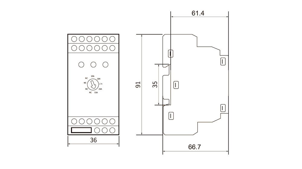
外形尺寸(毫米)
立即询价!
亿腾致力于为我们的客户提供最优质的服务!


中国安徽省芜湖市湾沚区安徽新芜经济开发区芜屯快速通道770号。
网址:www.etek-electric.com
浙江省温州市乐清市经济开发区纬⼗七路288号
中国安徽省芜湖市湾沚区安徽新芜经济开发区芜屯快速通道770号。
COPYRIGHT © 2024 浙江亿腾电气科技有限公司 ALL RIGHTS RESERVED